58. Square net cage
The identification tag for this tutorial is PDS-ABR. Pregenerated input files for this tutorial are found in the folder named PDS-ABR in the provided tutorial input files.
58.1. Tutorial overview
This tutorial covers:
- Creating a net cage from net panels
- Connecting a net panel to a rigid body
- Connecting a net bottom to multiple nets
- Connecting rib lines to net panels
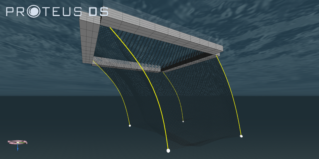
Fig. 58.1 Net cage with corner rib lines
58.2. Creating rectangular net panels
- Create a new project.
Note
- The net state will be defined using the net panel option. This requires four planar coordinates to define the corner nodes of a 4 straight sided net panel.
- Create five (5) 10 m by 10 m net DObjects named Bottom, Panel1, Panel2, Panel3, and Panel4.
- Define their states as shown in Fig. 58.2 through Fig. 58.8 using the panel method in the Define State dialogue. Ensure that your node coordinate definitions match those given in the figures.
Note
- A schematic of how you have setup your net cages with net edges and net corner nodes labeled is useful to minimize connection difficulties.
- Verify that the net panels have been arranged correctly to created a cube net cage in the visualizer.

Fig. 58.2 Tutorial net cage overview

Fig. 58.3 Net cage dimensions

Fig. 58.4 Net cage panel 1

Fig. 58.5 Net cage panel 2

Fig. 58.6 Net cage panel 3

Fig. 58.7 Net cage panel 4

Fig. 58.8 Net cage bottom panel
58.3. Creating a connection between the bottom net panel and the net cage walls
Note
- To avoid circular dependencies, the bottom net panel should be the master connection with all net cage walls.
- Add a connection of type DNetDNetEdgeConnection between the bottom net panel and each of the four net cage wall panels (four connections in total) where the bottom net panel is the master DObject in all connections.
Note
- To specify which arc length of the edge to control, the
$DNetFollowerArcSpanproperty is used.
- Specify the connection between the Bottom and Panel1 as:
// Mechanical
$DNetFollowerEdge 0 1
$DNetFollowerArcSpan 0 10
- Specify the connection between the Bottom and Panel2 as:
// Mechanical
$DNetFollowerEdge 3 1
$DNetFollowerArcSpan 0 10
Note
- When making the connection between Panel3 and the bottom net panel, note that node (0,0) of Bottom is connected to node (M,N) of Panel3 so the
$DNetFollowerArcSpanmust span from 10 m to 0 m along edge 1 of Panel3. The similar pattern arises for the connection between the bottom net and Panel4.
- Change the configuration of the connection between Bottom and Panel3 as:
// Mechanical
$DNetFollowerEdge 1 1
$DNetFollowerArcSpan 10 0
- Change the configuration of the connection between Bottom and Panel4 as:
// Mechanical
$DNetFollowerEdge 2 1
$DNetFollowerArcSpan 10 0
58.4. Adding rib lines
Note
- Lines are often sewn into nets to provide structural support. These lines can be created using four cable DObjects.
- This tutorial will model rib lines using separate cable DObjects, however this can also be done using the Net extCable feature. This is described in the Net extCable feature tutorial.
- Create four cable DObjects named Rib12, Rib23, Rib34 and Rib41.
- Define their states to be as shown in Fig. 58.9.

Fig. 58.9 Rib line schematic
- Create an edge connection between Rib41 and edge 2 of Panel1.
- Specify the connection properties as:
// Mechanical
$DNetFollowerEdge 2
$DNetFollowerSpan 0 10
- Make an edge connection between Rib41 and edge 3 of Panel4
- Specify the connection properties as:
// Mechanical
$DNetFollowerEdge 3
$DNetFollowerSpan 0 10
- Repeat the above connection method for the remaining rib lines.
58.5. A first simulation run
- Set edge 0 of Panel1, Panel2, Panel3, and Panel4 to be static.
- Set
$CurrentProfileto 1 and add the$CurrentSpeedand$CurrentHeadingproperties. Set the current speed to some desired values (e.g. 0.5 m/s).
Note
- The current should deflect the net.
- Run a simulation for 10 seconds and observe that the rib lines become disconnected from the bottom net panel.
58.6. Creating rib line point connections with nets
Note
- In the previous section it was observed that the rib lines become disconnected from the bottom net, as seen in Fig. 58.10. The end nodes of cables should be explicitly connected to nets or rigid bodies when a rib line edge connection is made while there exists multiple nets connected to a single corner. The extra connection ensures that the rib line is fully constrained.
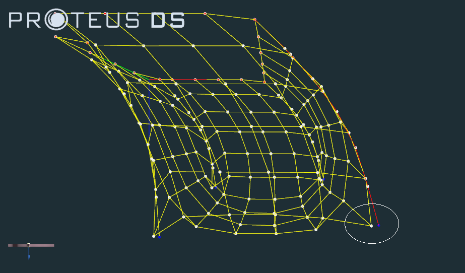
Fig. 58.10 Rib line becoming disconnected from net
Note
- The order that the net connections are made in ProteusDS can result in disconnections between rib lines, nets, and rigid bodies.
- For each of the rib lines, create a point connection to the bottom net. Note for each corner is share by two edges. Ensure the proper edge arc length is inputted for the connection based on the edge specified.
- Set the point connection between Rib12 and the bottom panel to be:
// Mechanical
$DNetFollowerEdge 0
$DNetFollowerArcLocation 10
$DNetFollowerEdgeLocation 10
- Define the connection information for the remaining 3 rib line point connections similarly.
- Once the connections between the bottom net and the rib lines have been made, re-run the simulation. Notice that the top of the rib lines are still disconnected.
- Constrain node 0 of each rib line and re-run the simulation.
58.7. Add a floating collar
- Remove the static edge and the node 0 static constraints for all four net cage walls and the rib lines, respectively.
- Add a RigidBody DObject to the simulation called Collar.
- Center the RigidBody at the center of the net cage (5,5,0) m.
- Add a RigidBodyCuboid feature called Floater to the feature Library.
- Set Floater’s dimensions to be 10 m in X, 1 m in Y, and 1 m in Z.
- Set all of the Floater’s model parameters to match the following:
// Added Mass Coefficients
$CAx 1
$CAy 1
$CAz 1

// Dimensions
$LengthX 10
$LengthY 1
$LengthZ 1

// Drag Coefficients
$CDt 0
$CDx 1
$CDy 1
$CDz 1

// Fluid loading
$WindLoading 1
$HydroLoading 1
$HydrostaticFroudeKrylov 1

// Mesh
$SegmentsX 10
$SegmentsY 3
$SegmentsZ 8

// Soil loading
$SoilLoading 1
- Create four Floater cuboid features around the outside of the net perimeter.
- Set Collar’s the properties to match the following listing:
// Mass properties
$Ix 172541
$Iy 172541
$Iz 341666
$Ixy 0
$Ixz 0
$Iyz 0
$DefineInertiaAboutCG 0
$CGPosition 0 0 0
$Mass 20500

// Numerical
$Kinematic 0

$Cuboid Floater -5.5 0 0 0 0 90
$Cuboid Floater 0 5.5 0 0 0 0
$Cuboid Floater 5.5 0 0 0 0 90
$Cuboid Floater 0 -5.5 0 0 0 0
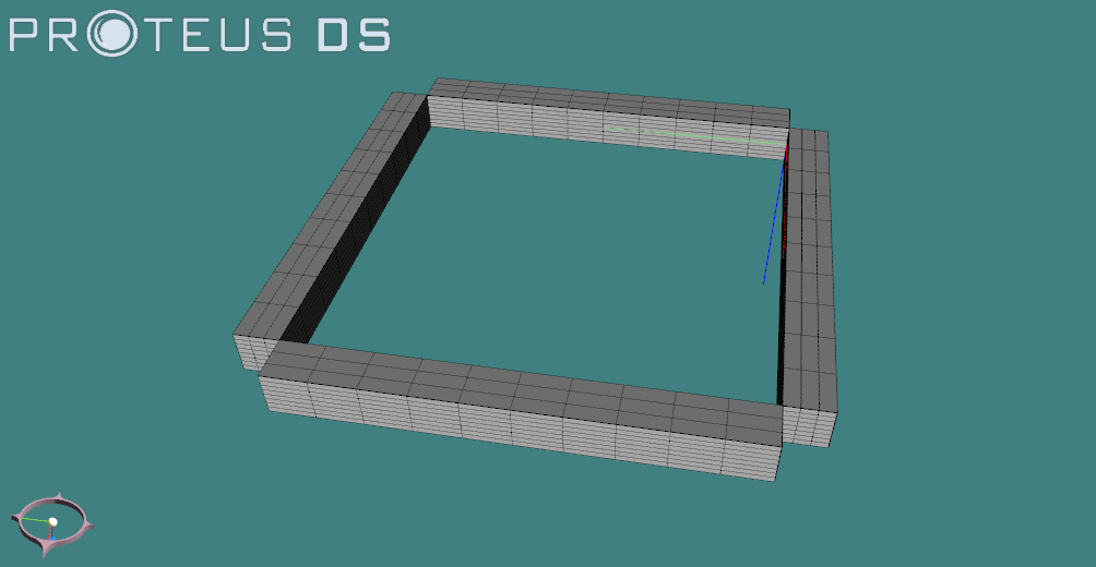
Fig. 58.11 Net cage floater
58.8. Connecting the net edges to the floating collar
- With the Collar as the master DObject, make an edge connection to Panel1.
Note
- For a RigidBody to net edge connection, the edge of a net panel is constrained along a straight line distance between two points on the RigidBody. To constrain net Panel1 to Collar, use the following connection properties:
// Mechanical
$NetEdge 0
$RigidBodySpan -5 -5 0 -5 5 0
$NetEdgeSpan 0 10
- Make similar connections between Collar and the remaining 3 net panels (all along their edge 0, adjusting the
$DNetFollowerSpanfor each connection).
Note
- The rib lines are controlling the net panel corner nodes and are themselves not constrained. The rib line end nodes will be constrained by a point connection to the RigidBody.
- Make a point connection with the Collar as the master to Rib12.
- Set the connection’s parameters to the following:
// Mechanical
$DCableFollowerNodeN 0
$DCableFollowerLocation -5 5 0
- Make similar point connections between the Collar and the remaining 3 rib lines.
- Add a clump weight at the end of each of the rib lines using the ExtMass feature.
- Make the clump weight 0.25 m in diameter with a density of 2000 kg/m2.
- Run the simulation again.
- Option 1: Try simulating the net cage in waves.
- Option 2: Try setting the
$Kinematicflag to 1 for the Collar to prevent movement of the cage in current. - Option 3: Try adding mooring lines to the Collar and simulating the response of the floater to waves and current.
Note
- A hydrodynamic database may be required to properly estimate wave loads (radiation and diffraction effects) on the floater since floaters are often large relative to the incident wave length.